What is a Fired Heater?
Fired Heaters are responsible for heating process fluids in Oil Refineries and Petrochemical plants, during the refining and manufacturing of chemicals.
There are a number of different types of fluids that may requiring heating, such as Crude Oil, Hydrocarbons, Hydrogen, Water and Steam. These process fluids will flow within tubes usually located around the internal inner wall, whilst burners produce large flames in the centre of the chamber.
Fired Heaters are sometimes referred to as Furnaces within the Oil & Gas industry, which has often resulted in some confusion.
The three main sections of a Fired Heater is as follows:
- Radiant Section
- Convection Section
- Stack
What is the Radiant Section?
The Radiant Section contains the burners and tubes usually located along the inner walls, with the heated fluid flowing inside. The Radiant Section will be the hottest part of the heater, with temperatures typically between 700 C (1292 F) to 900 C (1620 F). The primary mode of heat transfer within this part of the heater is via radiation.
What is the Convection Section
The hot flue gas from the Radiant Section is routed to the Convection Section which consists of multiple tube bundle rows with the hot flue gas flowing over the rows.
The Convection Section is primarily responsible for increasing the overall efficiency of the heater, since the hot flue gases from the radiant section is used to for further heat energy transfer before exiting to the atmosphere.
The primary mode of heat transfer within this part of the heater, is convective.
What is the Stack?
The Stack or Chimney, is responsible for allowing the hot flue combustion gases to be safely expelled into the atmosphere. The Stack will also play a role in creating the 'draft effect' within the heater, in order to pull the flue gases through the heater until the stack exit point. This phenomenon is often referred to as the 'Chimney Effect'.
Types of Fired Heaters
Fired Heaters can be distinguished by the different external appearance of their Radiant Sections. There are three main distinctions referred to as Vertical Cylindrical, Cabin and Box Heaters.
.
What is a Vertical Cylindrical Heater?
Vertical Cylindrical heaters, often called 'VCs', consists of a cylindrical radiant section, with the Convection Section mounted above the Radiant. The Radiant coils usually consist of vertically arranged tubes in a serpentine layout, around the inner walls of the chamber.
These are perhaps the most common fired heater design in recent years, likely due to their cost efficient layout, relative ease of transportation and smaller footprint.
Vertical cylindrical heaters are commonly used for utility feedstocks such as Thermal Oils and Ethylene Glycol, but are also used for Reboiler and Reactor Feed services.
With most of the refractory surface inside the heater being shielded with coils, contributes to the cost efficiency of the layout and smaller footprint in comparison to the other fired heater design options.
What is a Cabin Heater?
Cabin heaters have a cubic Radiant Section with the horizontal tubes arranged against the inner walls. Usually, two walls not have tubes located on them, allowing for observation doors to clearly see the burner flames during operation. In some cases, some tubes can also be located on the roof to maximise the available space used for heat transfer.
This design of fired heater is often the preferred choice for crude feedstock process fluids. The horizontal coils means that the process fluid can be readily drained for maintenance and cleaning activities.
The ability to readily drain and clean tubes is an important maintenance activity for Crude Heaters, as a internal coke / fouling layer deposit inside the tubes during operation.
The Cabin Heater design is typically characterised by wall mounted coils along the longest side of the firing box, with the end walls left clear for viewing ports.
Cabin heaters are also inherently more capable to mount larger convection sections than VC heaters, which can be a preferred when designing fired heaters with larger duties.
What is a Box Heater?
Box heaters are physically similar in appearance to Cabin Heaters, since the Radiant Section is also a cubic shape. However, the radiant tubes are vertically aligned in a serpentine layout around the internal walls.

For example, similarly with Cabin heaters, the Box Heater design is also inherently capable to mount larger convection sections to accommodate large duty requirements. In addition, similarly with VC heaters, the Box Fired Heater design also benefits from a cost efficient tube support configuration.
However, one of the downsides of having vertical tubes is that the process fluid is not readily drainable, which can be a very important requirement for fluids that are prone to coking.
Combustion and Fuels
Fired heaters are equipped with burners that can burn either gaseous fuels, liquid fuels, or both. As with other industrial combustion processes, it is important to control the amount of excess air for overall energy efficiency and stable combustion.
Combustion is a chemical reaction between a fuel and oxygen, resulting in the combustion flue gas products and release of heat energy.
With hydrocarbon fuels, the combustion products will primarily be Carbon Dioxide and Water.
For example, considering the combustion reaction of Methane:
CH4(g) + 2O2(g) → CO2(g) + 2H2O(g)
Sub-stoichiometric combustion of Methane
The chemical equation above shows a stoichiometric balance equation, whereby the reactants are in molar balanced ratios. However, in industrial combustion processes, combustion control is not maintained at this delicate balance.
Sub-stoichiometric combustion conditions actually results in the production of Carbon Monoxide, which is a dangerous and potentially deadly if inhaled by humans.
2CH4(g) + 3O2(g) → 2CO(g) + 4H2O(g)
Sub-stoichiometric combustion of Methane
In order to avoid sub-stoichiometric conditions, an excess amount of air is usually provided to ensure that combustion is stable and CO production is avoided. However, as you raise the level of excess air the overall fuel efficiency is also generally reduced.
For delivery of combustion air, fired heaters are designed as either Natural Draft or Forced Draft. API 560 has specified the excess air % (wt:wt) to be used depending upon whether the burners are operating via Natural Draft or Forced Draft. The following sections will describe the arrangements of each option.
Combustion NOx
The term 'NOx' refers to the combustion products Nitric Oxide (NO) and Nitrogen Dioxide (NO
2), which are the most relevant for environmental pollution concerns. These gases contribute to the formation of smog and acid rain.
NOx formation occurs during high temperature (>1300 C / 2600 F) oxidation of nitrogen molecules. The source of the nitrogen molecules can be either from the air composition or fuel composition. NOx formation originating from the air is referred to as Thermal NOx.
Thermal NOx
The formation of NOx from the combustion air is a function of the temperature and the residence time of Nitrogen at that temperature. The process involves the dissociation of Nitrogen and Oxygen molecules, which then undergo a series of reactions:
N2+ O ⇌ NO + NN + O2 ⇌ NO + ON + OH ⇌ NO + H
Fuel NOx
The mechanism for the formation of NOx from Nitrogen within the fuel source is not fully understood, but consists of primarily two main reaction pathways. The first pathway involves the oxidation of volatile Nitrogen free radicals to form NO, whilst the second route occurs more slowly and involves the combustion of the solid hydrocarbon components of the fuel.
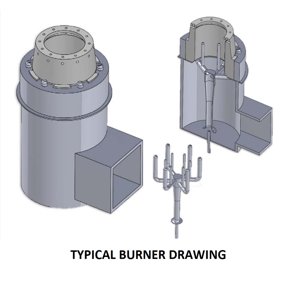
Process Burners
Fired heaters will utilise particular type of burners referred to as 'Process Burners', which are developed and supplied by specialist vendor companies. Process burner supply companies will have their own propriety design modifications to enhance combustion performance whilst minimizing emissions.
Traditionally, the two main design options are referred to as 'Staged Fuel' and 'Staged Air' designs. In this section, we will not discuss the details of each design option.
Fired Heater Draft
During operation, the internal pressure (draft) within the fired heater should always be negative. This means that when operators open the observation doors to view the flames, the hot flue gas will not be expelled and potentially seriously injure personnel.
The draft within the heater is primarily controlled by the Stack (for natural draft heaters) or an induced draft fan.
Natural Draft
Natural Draft Fired Heaters have burners whereby combustion air is entrained into the wind-box of each burner directly from the atmosphere. The amount of air entering is determined by the draft (negative pressure) levels maintained within the heater.
During the design stage, fired heater and burner design engineers will need to ensure that the stack is stable sized to create sufficient draft to pull an adequate amount of air during the various operation cases. Calculation of the burner pressure drop of the air flowing through the burner is a key part of this design process.
Natural Draft heaters are typically designed to operate with between 15% to 25% excess air
Forced Draft
Forced Draft Fired Heaters utilise a Fan to control the delivery of combustion air to the burners. Utilising this forced draft fan (FD Fan), the amount of air flowing for combustion can be controlled with a greater degree of accuracy. Therefore, Forced Draft heaters are often designed with lower excess air levels (typically between 10% to 15%), thereby increasing the overall energy efficiency.
In addition, Forced Draft configurations often include an Air Pre-Heater, whereby the air flows is warmed via a heat exchanger before entering the burners. The hot flue gas leaving the convection section is actually utilised as the hot medium for the heat exchanger.
This can greatly improve the efficiency of the fired heater, often achieving between 90% to 95% efficiency.
Note that forced draft heaters, the combustion air fan should be designed to overcome the pressure losses of the air ducting, Air pre-heater and the burners, therefore a positive pressure should not be created in the Radiant Section.
Image from API 560 Fired Heaters for General Refinery Service
Balanced Draft
Similar to a Forced Draft configuration, a Balanced Draft system will also have a FD Fan and with an additional Induced Draft Fan (ID Fan). The role of the ID fan is to pull the flue gas to overcome the pressure losses in the convection section.
The Balanced Draft system often also incorporates the use of an Air Pre-heater (APH), whereby the hot flue gas from the convection section is used as the hot medium in the APH heat exchanger to warm incoming combustion air. The APH will significantly increase the overall energy efficiency of the fired heater.
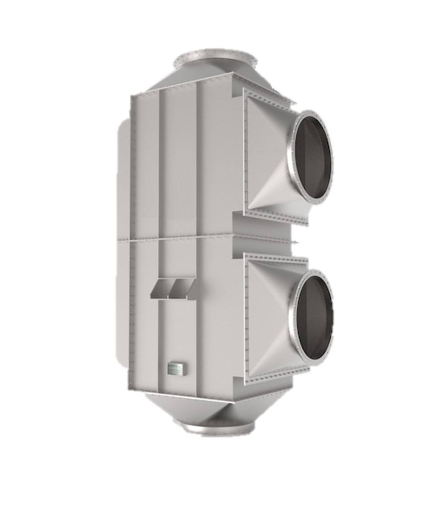
Air Pre-Heater
To maximise the efficiency, a Fired Heater can be designed with an Air Pre-heater (APH), which is a heater exchanger to warm the incoming combustion air before it enters the burners. The hot flue gas leaving the convection section is actually utilised as the hot medium for the heat exchanger.
Example of a Flue Gas - to - Air Pre-heater
Fired Heaters with APH systems can greatly improve the energy performance, often achieving between 90% to 95% efficiency.
Traditionally, cast iron Air Pre-heaters have perhaps most commonly been used, however, in recent years APH systems utilise various types of heat exchange designs, including the Plate Type Air Pre-heaters.
In some cases, the APH system will be comprised of two heat exchangers, the main Flue Gas-to-Air APH, and an additional Steam APH. The Steam APH (SAPH) utilises Steam as the hot medium to increase the air temperature from ambient conditions to temperatures typically between 50 C to 70 C (122 F to 158 F), before it then subsequently enters the main Flue Gas-to-Air APH.
Example of Steam Air Pre-heater
Utilising a SAPH contributes to further optimizing the fuel efficiency of the Fired Heater. The Steam utilised as drawn from existing Steam services available at the plant. Therefore, in cases where steam is not available, utilising a SAPH will not be feasible.
Process Coils
The term 'coils' refers to the arrangement of tubes and return bends which contains the flowing process fluid to be heated. The coil material and wall thickness required will depend upon the heater's particular performance requirements, fluid corrosiveness, pressure and temperatures.
For selecting the process coil design, the following design standards are commonly used:
- API 530 - Calculation of Heater Tube Thickness in Petroleum Refineries
- ASME I and VIII Boiler and Pressure Vessel Code
The following is a list of the common coil materials utilised within API 560 Standards - Fired heaters for General Refinery Service:
Material
|
Pipe Grade
|
Carbon-0.5Mo
|
A335 Gr P1
|
1.25Cr - 0.5Mo
|
A335 Gr P11
|
2.25Cr - 1Mo
|
A335 Gr P22
|
3Cr - 1Mo
|
A335 Gr P21
|
5Cr - 0.5Mo
|
A335 Gr P5
|
5Cr - 0.5Mo-Si
|
A335 Gr P5b
|
9Cr - 1Mo
|
A335 Gr P9
|
9Cr - 1Mo-V
|
A335 Gr P91
|
18Cr - 8Ni
|
A312 TP 304/304H/304L
|
16Cr - 12Ni-2Mo
|
A312 TP 316/316H/316L
|
18Cr - 10Ni-3Mo
|
A312 TP 317/317L
|
18Cr - 10Ni-Ti
|
A312 TP 321/321H
|
18Cr - 10Ni-Nb
|
A312 TP 347/347H
|
Nickel Alloy 800H/800 HT
|
B407
|
25Cr-20Ni
|
A608 Gr HK40
|
Tube Surface Area
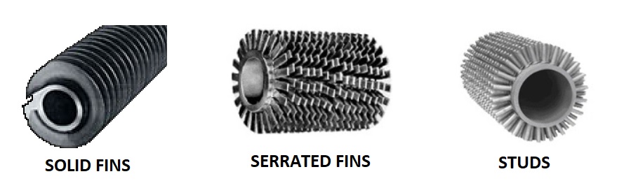
The coils within the Radiant Section will consist of bare tubes, whereas the tubes within the Convection Section usually consists of a combination of bare and either finned or studded tubes.
The fins and studs on the tubes act to increase the surface area for heat transfer. The size and density of the fins or studs needs to be carefully considered in accordance with the flue gas temperatures at each row. If the extent of finning is too high at a particular flue gas temperature, this can result in excessive heat flux and coil damage.
Studs are selected when the fired heater uses liquid fuels such as fuel oils, where there is a more frequent requirement for cleaning the external coil surface due to soot deposits. The arrangement of the studs allow for easier cleaning than finned tubes.
Coil Supports
The coil support design may vary between heater manufacturers, however, the general approaches will fall into the following:
- Top Supports: used for vertical aligned coils, utilising hanger supports which hold the coil at the upper return bends. The supports themselves are located at the radiant arch/roof or upper wall.
- Bottom Supports: used for vertical aligned coils, utilising hanger supports which hold the coil at the lower return bends. The support themselves are located at the heater floor.
- Horizontal supports: used for horizontally aligned coils where the coil is supported at the extreme terminal points and along the tube length if necessary. This philosophy of support is used for both Radiant and Convection section tubes, although the mechanical design and style will vary significantly between these sections.
API 560 standard specifies that the maximum allowable distance between the supports of horizontal tubes should be 35 x Tube Outside Diameter (OD), or 6m, whichever is less.
UOP Design Code specifies that this distance should not exceed 30 x Tube Outside Diameter (OD).
The following table details the maximum permitted flue gas temperatures for each coil support material.
API 560 specifies that 100 C (180 F) margin should be applied to the calculated flue gas temperatures calculated of the radiant tube supports.
For the convection tube supports, API 560 specifies that 55 C (100 F) margin should be applied to the calculated flue gas temperatures calculated for the convection section rows.
Where the tube supports are exposed to the hot flue gas of the radiant section (i.e. they are not covered by any refractory material), the minimum material grade shall be 25Cr-12Ni.
Flow Passes
The process coil arrangement will often be split into identical flowing paths, referred to as 'passes'. In most instances, the passes will remain completely segregated for the entire circuit within the heater, thereby creating somewhat of a symmetrical heat transfer profile for each pass.
Consequently, the number and type of tubes will be identical at each corresponding section of each pass. Splitting the process flow into passes, can help to reduce the overall pressure drop of the process fluid within the heater, since splitting the flow reduces the velocity flowing within the tubes. Adjusting the tube diameter of the tubes within the fired heater will also affect the process pressure drop, since the cross sectional flow area will be altered which in turn impacts the velocity within the coils.
Pressure Drop
The pressure drop of the process fluid flowing within the coils is an important parameter that must be considered for Fired Heater design and operation. For single phase process streams, where the fluid phase remains as either 100% liquid, or 100% vapour, the pressure drop can reliably be calculated with a good degree of accuracy.
The pressure drop within the pipe for single phase flow characterized by the Darcy–Weisbach equation:

where the pressure loss per unit length Δp/L (SI units: Pa/m) is a function of:
 , the density of the fluid (kg/m3)
 , the hydraulic diameter of the pipe
 , the mean flow velocity, experimentally measured as the volumetric flow rate Q per unit cross-sectional wetted area (m/s);
 , the Darcy friction factor
However, in cases where vaporisation of the process fluid is required, there will exist two-phases (a combination of liquid and vapour flow). Calculation of the process fluid pressure drop under these circumstances is inherently less reliable.
Flow regime
For single-phase process fluids, the ideal flow regime should be typically Turbulent. It is important to for the fired heater design to ensure the avoidance of laminar flow is avoided across the entire range of operation, from turndown case to maximum operation cases.
The flow regime will have a direct impact upon the heat transfer coefficient of the fluid within the coils, thereby influencing the heat transfer capability.
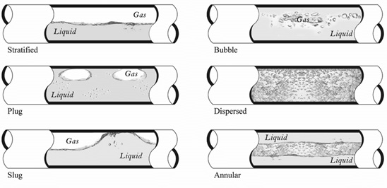
For two-phase process fluids, the flow regime may reasonably transition between several phases, such as bubble and wavy regimes. However, special effort should be made to completely avoid the Slug flow regime, which can result in vigorous movement of the coil and resultant mechanical damage.
Image from Figure 1 - uploaded by Usama Kadri, Cardiff University
Refractory Insulation
The internal walls of furnaces and process heaters are insulated with refractory lining, helping to conserve heat loss and maintain the internal temperature inside the heater. In addition, the external casing of the heater needs to be cool enough for operating staff to access safely.
API 560 Refractory Design Requirements
API 560 Standard has specific requirements to be achieved for the external casing. These requirements are as follows:
- 90 C (195 F) at the floor
- 82 C (180 F) on the walls
- 0 m/s (0 mph) wind speed
- 27 C (80 F) ambient air temperature
Most common refractory materials
In modern process heaters, the most common type of refractory materials are as follows:
- Castable Refractory
- Ceramic Fibre Insulation
Example of Fibre, Bricks and Castable Refractories
Castable Refractory
Castable refractory has traditionally been used in process heaters for over 40 years. The process of installing this refractory involves mixing powder with water, applying this ‘wet-mix’ on to the required surfaces and then an extensive drying out procedure.
Traditionally, this refractory can be applied throughout all areas of the heater. However, in recent years, ceramic fibre has been used on the radiant section walls and castable applied elsewhere.
Ceramic Fibre
Fibre lining has been used increasingly with over the last 20 years. Fibre has a much simpler installation process and is significantly lighter than castable refractory, which has significant cost efficiencies for fabrication, assembly and shipment.
Although most commonly used in Radiant sections only, installation of fibre throughout all sections of the heater has become a more frequent occurrence. In some instances, a stainless steel mesh or thin plate is used to further secure the fibre position (particularly where high flue gas velocities are expected).
Fired Heater Instrumentation and Control
The instrumentation installed on fired heaters will have two main distinct objectives as follows:
- Stable and reliable performance control
- Safety monitoring and hazard mitigation
The operation of fired heaters presents inherent fire and explosion safety hazards which must be monitored and at all times.
In recent years, safety experts generally recommend that separate instrumentation and control loops should be segregated between these two objectives. This allows the safety shutdown system to remain somewhat independent and take the appropriate action upon detection of a hazard.
Firing Rate Control
The most common method of control is adjustment of the firing rate (i.e. fuel pressure) in order to achieve a defined process outlet temperature set-point. The fuel supply line will have a main fuel control valve that will open/close as required, adjusting the fuel pressure supplied to the burners to raise/lower heat release to achieve a process outlet temperature set-point.
This control loop will consist of the temperature thermocouple on the process outlet line, a fuel pressure controller logic block and the fuel control valve.
The control for the API 560 Fired Heaters is usually handled by the refinery or petrochemical site facility DCS (Distributed Control System).
Burner Management System (BMS)
The Burner Management System is the safety shutdown system of the fired heater. The primary tasks of the BMS is to constantly monitor various parameters that may pose a safety threat. BMS will take a prescribed mitigative action (i.e. Trips) if any of these parameters are detected outside of defined safety limit setpoints.
Common Safety Parameters Monitored by BMS
- Main Fuel Pressure
- Pilot Fuel Pressure
- Main Flame presence
- Pilot Flame presence
- Arch Temperature
- Tube Temperature
- Process Flow Rate
Alarm System
Each of the parameters mentioned above (except the flame detectors) will usually have an associated Alarm to notify operators of an 'unhealthy' condition before progressing to a particular Trip action. The Alarm and Trip setpoints should be sensibly defined to allow the operators suitable time to take mitigative action in order to bring the heater back into a safe operating condition.
.png)


Comments
Post a Comment